QRP Labs QMX+ build
29/09/2026
For me, this hobby is about technique and homebrewing. I've followed QRP Labs for a long time and have already built a QCX+ for 40m and a QMX low-band version (80-20m). The design philosophy fits what I want from a radio: compact, well documented, and open to modification. It also follows the KISS principle (keep it simple, stupid), which for me is part of what QRP is about: doing a lot with simple means.
The QMX+ is the logical next step. It covers 160-6m and does CW, digital modes and SSB. It has an embedded SDR receiver, a built-in USB sound card, CAT control and a TCXO-referenced synthesized VFO. It runs the same firmware as the QMX but adds a desktop-style enclosure option, a battery-backed real-time clock and an optional internal GPS.
The build
A kit like this lets you build something serious with limited knowledge. All SMD components are factory-assembled, so what remains is the through-hole parts, and those go in quickly. Most of the real work is winding and mounting the toroids for the low-pass filters and the output transformer.
The optional GPS module plugs in at the top of the board, next to the antenna connector. A CR2032 on the front panel board keeps the real-time clock running.
I enjoyed it a lot. Because so much comes pre-populated, it's a weekend kit rather than a multi-week project.
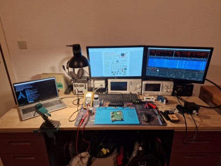
The workbench during the build, with the manual open for the toroid winding instructions.
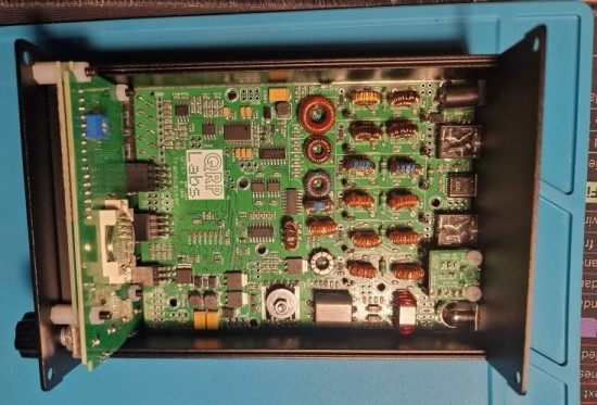
The QMX+ board mounted in the enclosure, with the optional GPS module at the top. The toroids are not yet glued at this stage.
Troubleshooting: one bad solder joint
After assembly I had exactly one problem, and it was my own doing. One of the output transformer joints made no electrical contact. I had burned the enamel off the magnet wire, but not completely. As a result, the BS170 PA transistors weren't getting any supply voltage.
The photo shows the underside of the board. The joint on the right is what a good joint looks like: a smooth, shiny bead. The one on the left is dull and irregular. The copper wire sits in a dimple without being properly wetted by the solder, and you can see remnants of the enamel next to the pad.
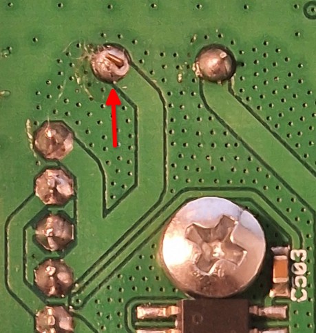
Underside of the board: the bad joint (left) next to a good one (right).
With a scope this was quickly debugged: no supply on the PA, trace it back, find the joint. Lesson learned: make sure the enamel is fully removed, tin the wire end first, and check continuity before powering up.
The PA modification
The QMX+ final stage is a switching amplifier built around BS170 MOSFETs in a 2+2 arrangement. The BS170 is a small plastic TO-92 signal MOSFET (60V, 500mA, 830mW), so it has little margin at 5W.
I applied the modification by Roelof PA0RDT, also listed on the QRP Labs modifications page. It doubles the PA transistors to 4+4, so every original BS170 gets a second one in parallel. In Roelof's write-up this roughly doubles the output power and allows a higher supply voltage, or running the transformer intended for 9V builds at 12V. LA3ZA reports the same and made many FT8 contacts with it without problems. The extra BS170s are ordinary parts; I ordered mine from Mouser (part no. 512-BS170).
Mounting
I soldered the second set of BS170s directly on top of the original ones, leg to leg, so each new transistor sits in parallel with the one below it. This piggyback approach needs no extra PCB space.
The kit clamps the PA transistors under a washer with a bolt and nut, which serves as heatsink and mechanical support. For the second set I added an extra washer and used a longer bolt, so that each set of transistors has its own washer and the whole stack is clamped together. The BS170 has a plastic body, so the washers are electrically isolated from the transistors.
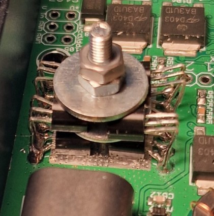
The PA: the second set of BS170s stacked on the first, clamped with a longer bolt and two washers.
Supply voltage and power
I built the WTST output transformer, the standard one for 9V builds, but run the radio from 12V. Roelof's write-up describes the same combination for the doubled PA. I set the PA voltage in the menu to 9.6V, which gives me 5W output on most bands. On four bands 5W is out of reach: even with the PA voltage at its maximum and a 12.6V supply, I measure about 4.9W on 17m, 3.7W on 12m, 4.7W on 10m and 3.6W on 6m.
Trade-offs
The extra transistors add gate and drain capacitance. LA3ZA mentions slightly reduced power on 6m for this mod, and on German QRP forums builders point out that the low-pass filters are designed around the capacitance of two BS170s, so extra capacitance can detune them on the higher bands.
That is why I checked the filters and the output. The QMX+ has a built-in filter measurement that you can run from the terminal. On 10m the low-pass filter is flat through the band and rolls off to about -20 dB around 39 MHz. On 6m it shows a slight peak below the band and rolls off to -20 dB around 70 MHz. I did not sweep the filters before the modification, so I have no before/after comparison, but there is enough passband left on both bands and I don't see a reason for concern.
I also measured the output with a spectrum analyzer, through a 30 dB attenuator into a dummy load. On 6m the only spur above the noise floor is the second harmonic, about 40 dB below the fundamental. At the maximum PA voltage, the output power ranges from about 3.6W on 6m to about 9.2W on 160m.
All the measurements are collected on a separate page: the low-pass and RF input filter sweeps and the output spectrum for every band, and a table with the maximum output power per band.
Glued toroids
I fixed the toroids on the board with TEC 7, a polymer-based assembly adhesive. It isn't the prettiest solution, but I find it safer, especially for portable operation, where a radio gets shaken around in a bag.
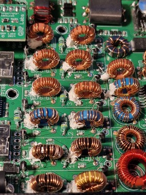
The low-pass filter toroids, fixed with TEC 7.
The finished board
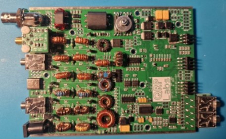
The finished QMX+ (board rev 4), top side.
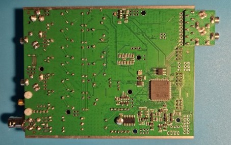
Bottom side, with the STM32 microcontroller in the centre.
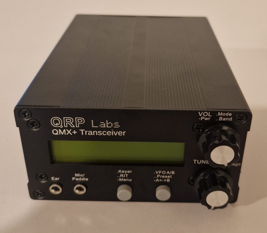
The finished QMX+ in its enclosure.
What's next
I still want to work out remote operation before putting the QMX+ into regular use. More on that in a later post.
73, Bert ON4DMD
Comments